☁️ Puffy Clouds Shader
Stylized Puffy Clouds Shader
A quick way of getting fluffy anime-esque clouds using a simple noise and vertex manipulation. Reasonably cheap technique, perfect for eerie backgrounds.
What are we building?
Here is a small preview for the final result of this shader. This scene is dressed up with some pretty crystals and ambience particles to display what it could be used for, but we'll be focusing on the clouds for this particular article.
Here you can see the clouds in isolation, using more neutral elements to showcase the depth fade:
Please keep in mind, we'll be using Amplify Shader Editor in this tutorial, but the knowledge and concepts behind it can be easily converted to Shadergraph, HLSL or Unreal's material editor.
We'll also be using the default built-in rendering pipeline, which again, can be easily converted, especially since this is a Unlit shader.
Graph Setup
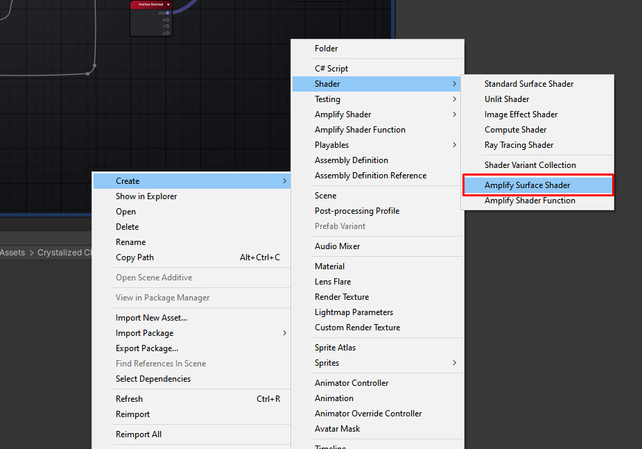
On Unity, let's make a new surface shader on Amplify. We'll call it Puffy Clouds.
Let's open that up and make sure some of the settings are properly set.
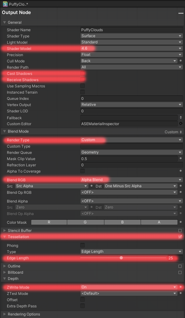
Only the highlighted options need to be set accordingly, let's go over them individually.
- Shader Model - Anything above 4.6 will work here. This is just so tessellation plays nice.
- Cast Shadows / Receive Shadows - You could leave these enabled, but I personally like to disable shadows to achieve the cel-shaded/anime-esque look.
- Render Type / Blend RGB - We just want to ensure we're doing the traditional alpha blend (Relevant for Depth Pass later).
- Tessellation - Make sure this is enabled. I use an Edge Length of 25, but this value will be exposed on a per-material basis, so we don't need to worry too much about it.
- Depth - Make sure we're z-writing.
I'll also make my shader unlit, but if you want it to be affected by lighting, you can.
Making the Puffiness
We achieve the puffiness of the clouds through vertex manipulation, meaning we change the position of each individual vertex of a given 3D model (in this case a plane) over time to shape it like a stylized cloud. We also apply tessellation to our cloud, which essentially generates new vertices in real time to fit our needs. This can mean a loss of control over how expensive the cloud gets, but if you are adapting this for a more performance sensitive project, you could always pre-subdivide the plane and drop the tessellation from the shader.
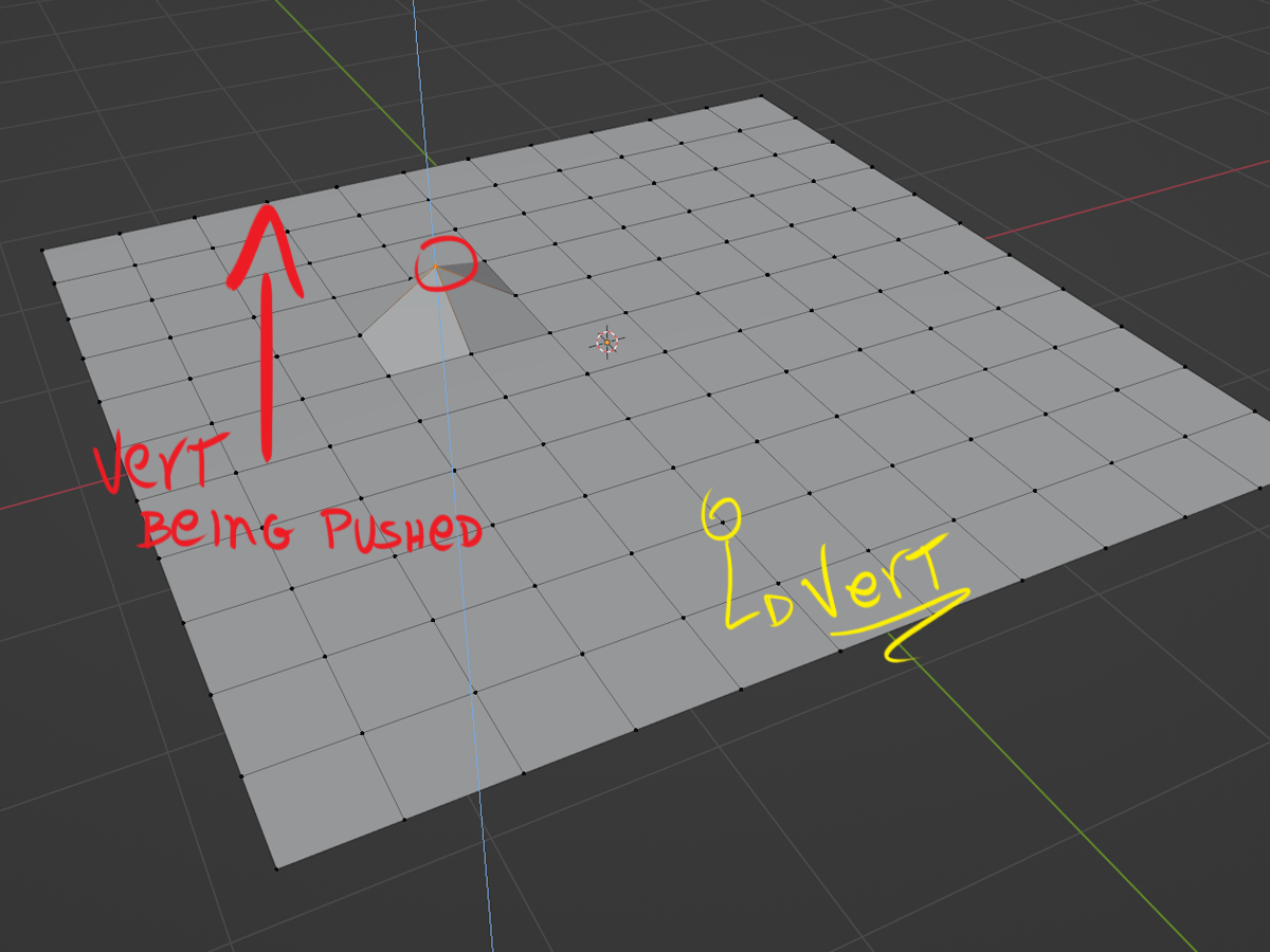
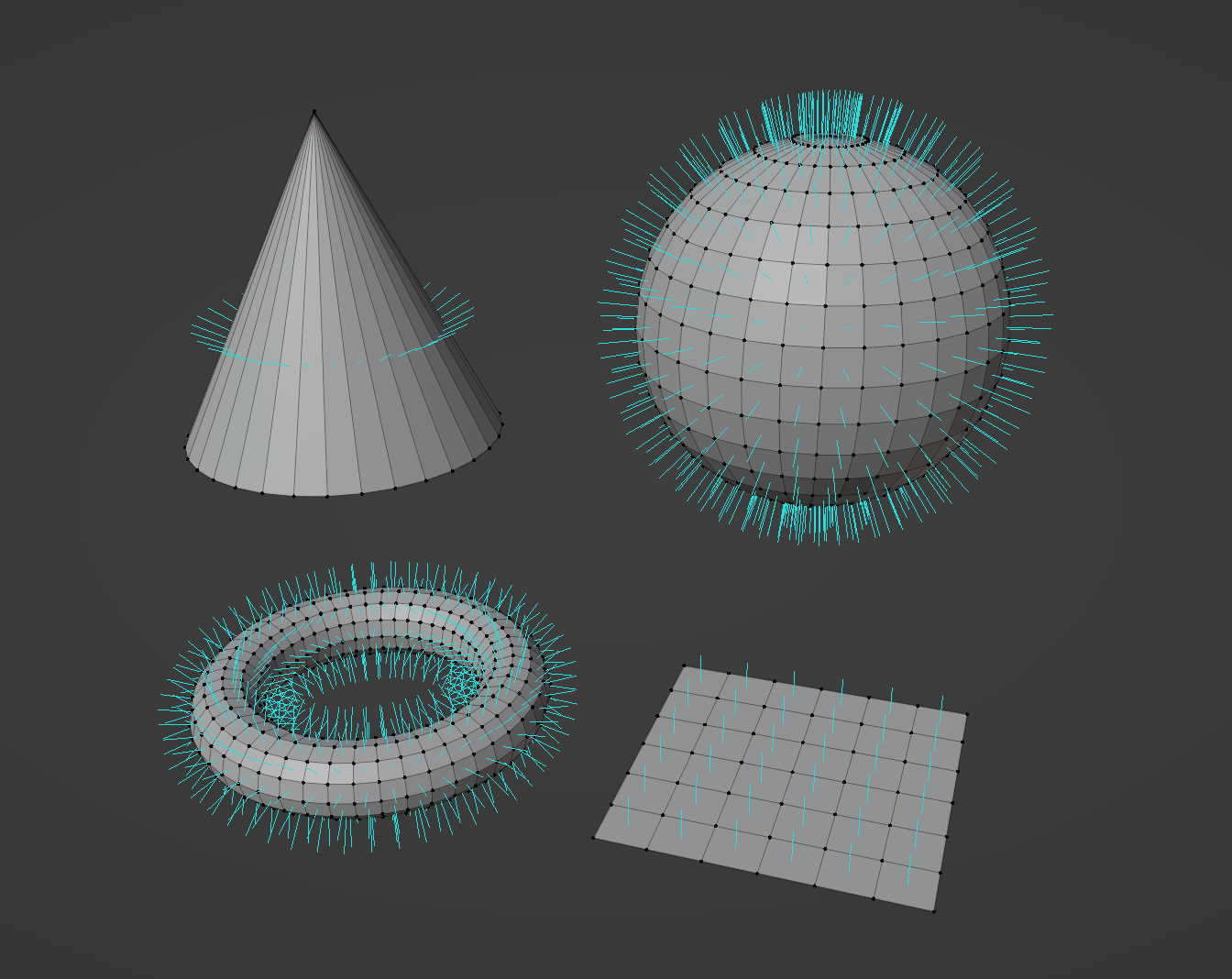
Vertex are the points in 3D space that define a model's geometry. In red we can see one being pushed upwards. This is what our shader will do, but with a lot more points.
So, let's make our vertex manipulation shader!
For this, we'll be using 4 layers of moving noises, the noises will control the height of each individual vertex point. Later, we'll blend all 4 layers together, which helps with the complexity of the cloud, and adds some nice "wrinkles" to the cloud.

The rule of thumb is that the brighter our noise, the more our clouds will "puff out", and the darker the noise, the less.
This means that white pixels will have most influence over our vertex data, and black pixels will have the least.
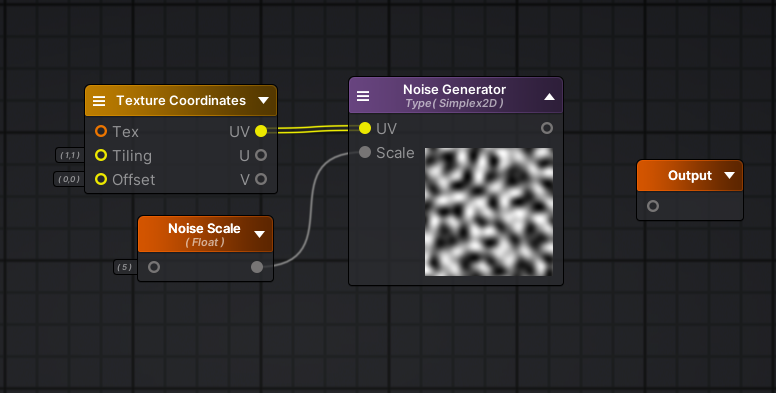
Let's make the layer function
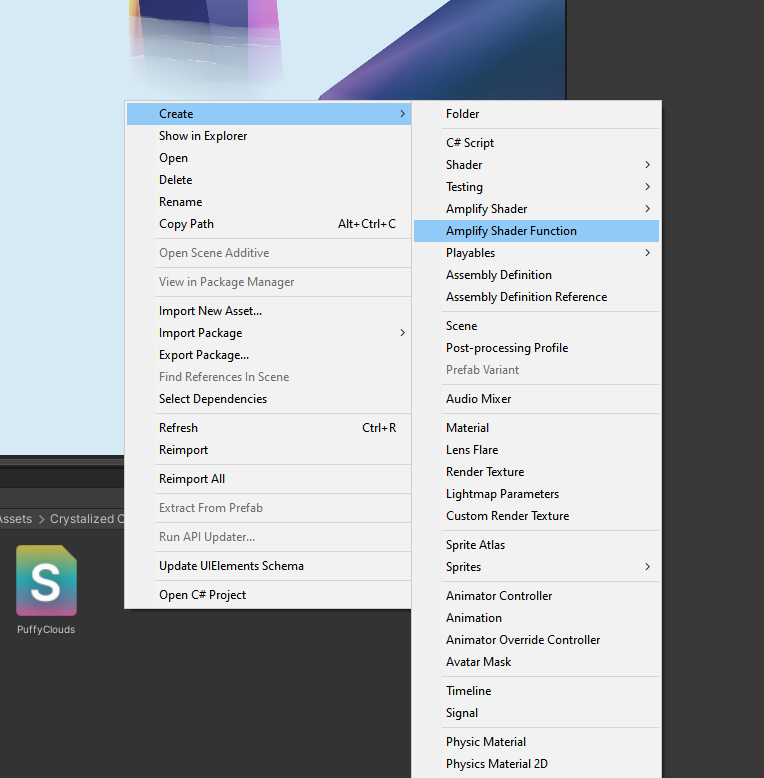
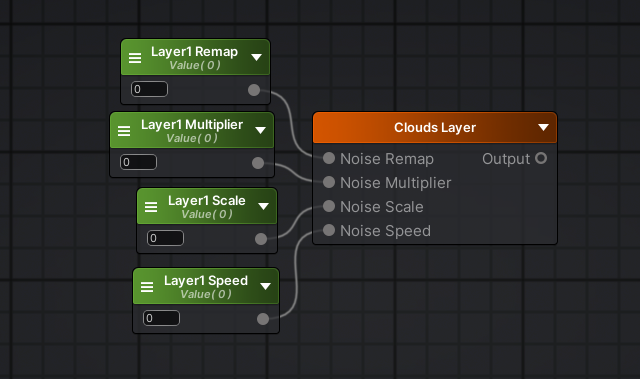
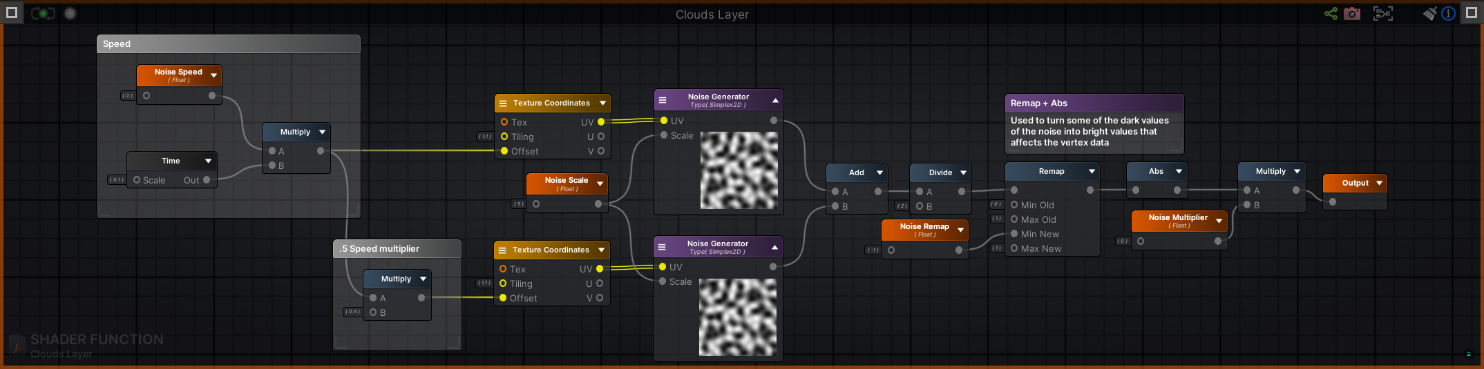
To avoid writing the same code on Amplify 4 times, let's make a shader function, I'll call mine Clouds Layer;
Inside the function, make a new Noise Generator node. You'll notice it will be completely gray. We need to feed the inputs for this node to make anything show up.
Let's start with the scale, this increases or decreases the size of the noise relative to the box, essentially how "zoomed in" we are. Make a new Function Input and name it Noise Scale.
You can change the name/settings of any node in Amplify by selecting the node and changing its settings on the left-side panel.
Finally, if you plug a Texture Coordinates node onto the UV input, you'll see that as you change the default value of the Noise Scale input, the noise preview will change accordingly. I'll leave it at 5 for now.
Your graph should look something like this now:
Now, to add extra complexity, let's duplicate everything except the Noise Scale and add them together by plugging both noises onto an add node.
This might seem redundant for now, but we want to make these noises move over time. So let's create a new Function Input and name it Noise Speed.
Our idea is to offset the noises by a given multiplier (Noise Speed) over time, then make one of the noises slightly slower, thus making our final addition a mishmash of different speed noises.
We can do this by multiplying our Noise Speed by a Time node, I'm also using the Time node on a .1 scale, since I want the clouds to be very slow moving.
Then we gotta ensure one of the noises is faster than the other, I did this by multiplying the bottom speed by .5, thus halving it.
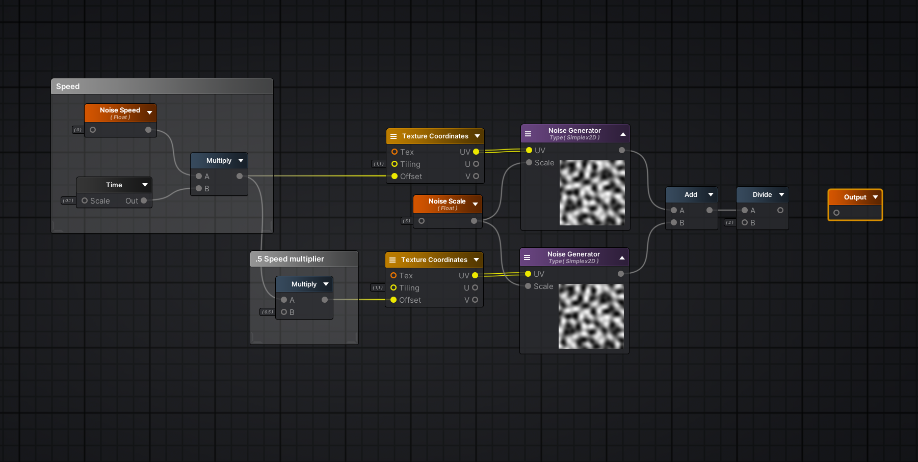
The noise generated ranges from 0 to 1. 0 means the vertex will be unmoved, while a value of 1 will raise the vertex upwards to generate the fluffiness. Since we're adding 2 noises together that have values peaking at 1, we'll inevitably have some parts of the result that will extrapolate the limit of 1 (2, 1.5, etc).
When we divide these values, we'll ensure that the highest possible value is always 1.
This would already work really well for a cloud layer. However, I'd like to add some extra knobs we can tune later.
First, let's add the option to make some darker parts of our noise influence the vertex data more meaningfully.
As you know, black pixels have no influence on the vertex data of our clouds, so we can turn these black pixels into negative pixels, then we can turn those negative pixels back into positive values. We can achieve this through Remap and Abs.
All remap does, is that it turns a given range of values into another given range of values linearly, think of it as a cross-multiplication operator for your shaders.
So, we can turn our black pixels into negative values by declaring a node structure like so:
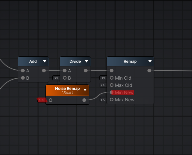
This means, our previous pixels with a value of 0 (black) are now -1.
Make sure to turn the Noise Remap into a Function Input so we can change its value later on our materials.
Remember I mentioned we'd turn the negative values onto positive values, so we could add that extra data as vertex displacement later? Well, to do it, you can simply add an Abs node after remap.
It gives you the mathematical Absolute value or Modulus of a given number. It is essentially "how far from zero is this number?" indicator. Meaning that the Modulus of 3 and -3 is 3! Since both are 3 numbers away from zero!
Essentially, we use Abs when we're not sure if the number is positive or negative. In our case, we'll never truly know if each individual pixel we're operating is positive or negative, so this rules out Negate as a viable option. As for multiplying the pixels by -1, we'd need to check for each individual pixel if they are negative before doing it, which is prohibitively expensive. Thankfully, basic arithmetics come in clutch with Abs to save the day.
Finally, we'll add a master multiplier that goes over the final result, we can promote that variable, calling it Noise Multiplier and plug the final result onto the final Output node.
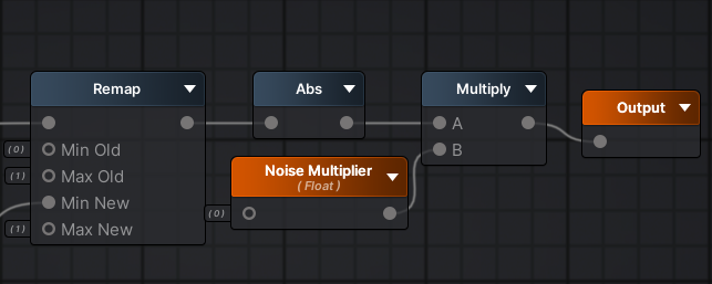
Your final graph should look like this:

Now, we are done with the function! If we go back to our original shader file, PuffyClouds, you can create a node with our function inside it by dragging and dropping the function from the file explorer, or by searching it on the node search!

Piecing our layers together
First, let's just create a matching set of variables to our shader so we can feed our function.
To do this, simply hold 1 and click anywhere on the graph. We want to make sure to change the newly created floats to properties, to make them exposed on our material later.
On the left side, you have Amplify's built-in inspector. Selecting a node will allow you to change its settings inside that panel. On the Type dropdown, you can change it from Constant to Property.
After making the matching set of variables, you can plug them in accordingly.
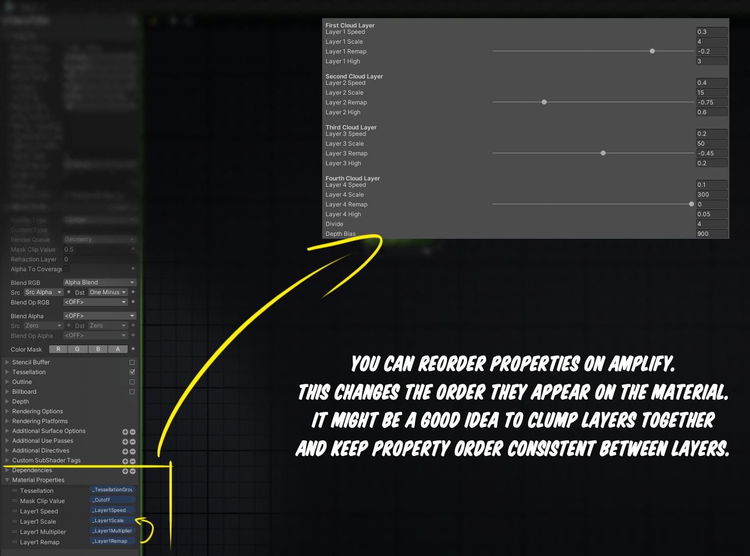
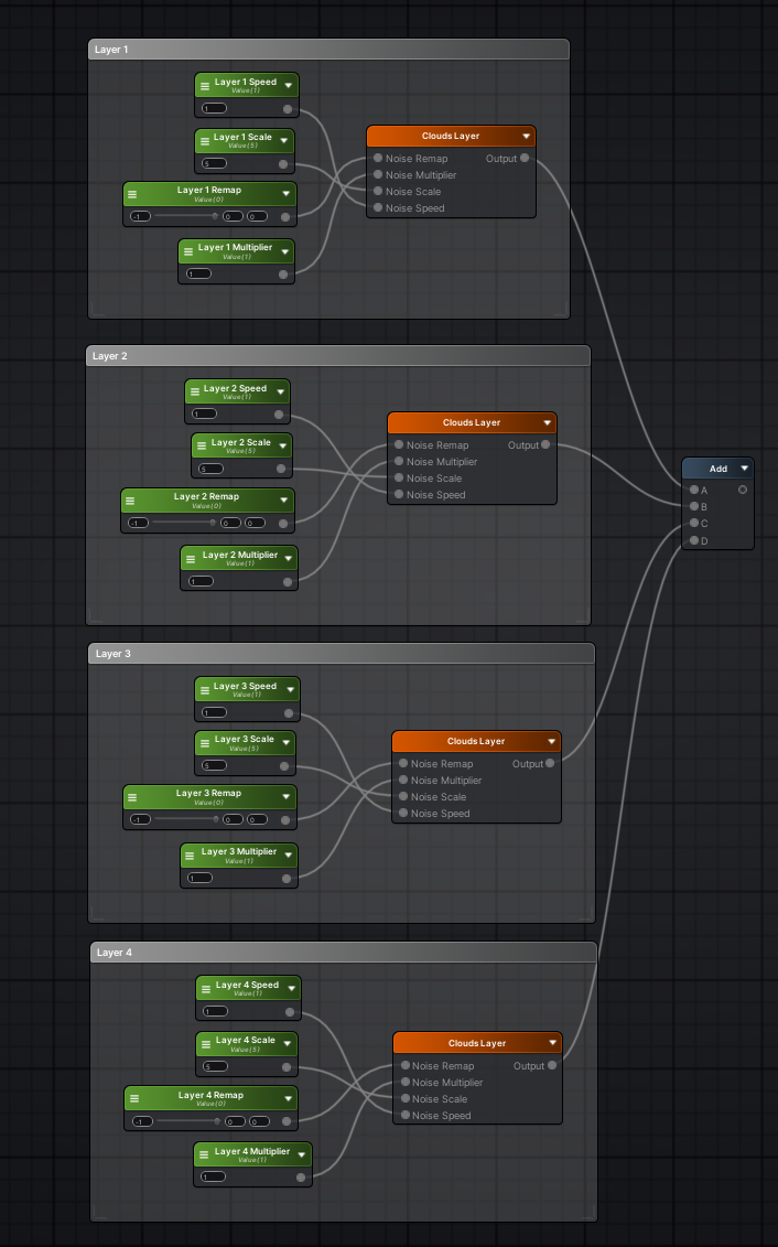
We'll be prefacing all of our variables with "Layer X", since we'll have 4 layers of vertex displacement.
Let's go ahead and repeat this process for all 4 layers. This means we'll have 16 properties on our material to start with, which can get a little messy. To avoid confusing materials, you can reorder the properties layout and clump the layers together as shown below:
Now, we'll add them all together like so:
If you want to test it out, you can plug them straight into the Local Vertex Offset entry of your shader, create a material using it and plug it into a plane:
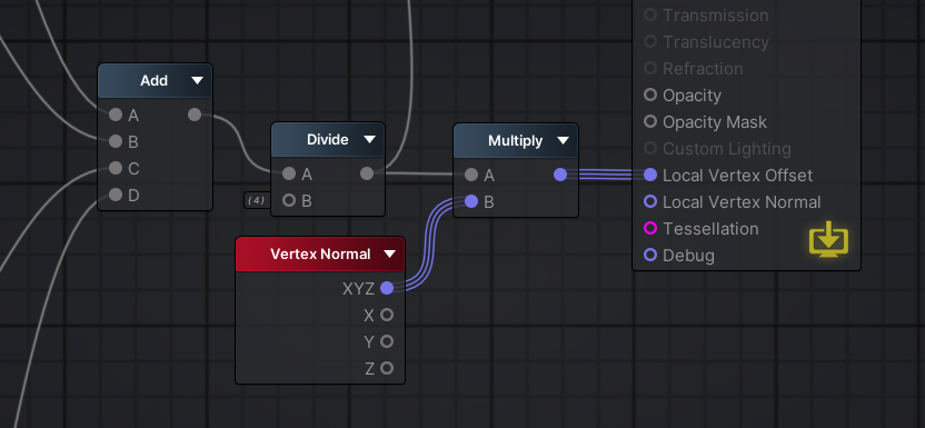
Something is clearly wrong. Aside from no color, the distortion of the plane is skewed and too extreme. This is because we added all of our layers (which contain lots of 1s) so some peaks are exceeding the value of 1, resulting in a extreme distortion on our plane. To fix this, we must divide our addition by 4, normalizing our values back to the baseline we want:Now, we need to make sure our distortion is going upwards and downwards, since right now everything has a slight tilt on distortion direction.
The proper way of doing this is by multiplying everything by the Normal Direction of the mesh's face.
The way the math behind this works, is that each individual piece of your place has an imaginary line that points towards a given direction. This line is used to calculate thing like reflections, but the data can be used to do custom shader behaviors such as this one.
A nice visualization of this can be done on Blender, here you can see many shapes with some blue lines sticking out of them, the blue line is the Normal Direction of their faces.
Notice how the plane has the normal direction going straight across it, exactly how we want it to be.
Our layers are now working as expected, this is really the hard part of the shader, it's smooth sailing from now on!
If you want, you can play with the material parameters to find variations that catch your eye!
Color & Transparency
The way we're handling color is by driving it along our vertex offset.
The same value we use to drive our vertices going up and down can be used to drive our color shifting from color A to color B. To do this, we need to a Lerp node.
Simply plug our combined layers onto the Alpha input of the Lerp node, then, create 2 color for the A and B inputs, like so:
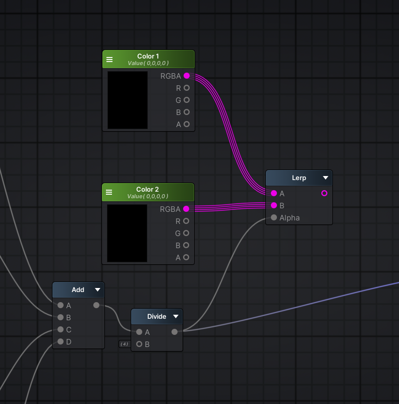
Make sure those colors are exposed to the material by turning them into a Property.
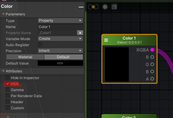
Before we jump into transparency, make sure to enable HDR on each color node by expanding the attributes panel on the Amplify inspector:
Now, if you plug that straight into emission, you'll be able to color your clouds on the material inspector.
These can be iterated rather quickly, so don't be afraid to experiment!
Arcane Cloud:
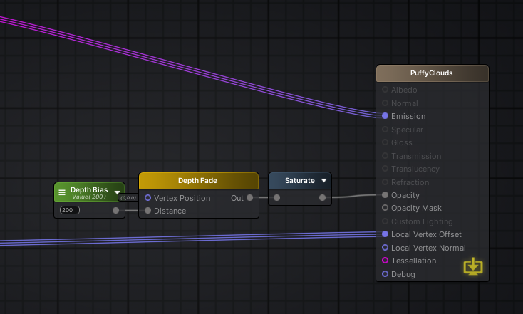
Poisonous Fume: ### Transparency We want our cloud to become fuzzy and fade away when it touches other surfaces, this removes the harsh lines where the cloud intersects with the crystals.To do this, simply add a Depth Fade node followed by Saturate on the emission of our shader.
Saturate is the same as Clamp, it makes sure our values are between 0 and 1.
The advantage of Saturate is that it is usually free, since it is supported by Microsoft's shader assembly, thus writable in a single instruction.
This doesn't mean that all GPUs can write X in equal speed to Saturated X, but most GPUs which support DirectX should be able to.
We also want to create an exposed float variable, called Depth Bias, which we'll use to control how harsh the fade will be. Plug that into the Distance input of our Depth Fade node.
Now, our clouds are working as expected:
And our final graph looks like this: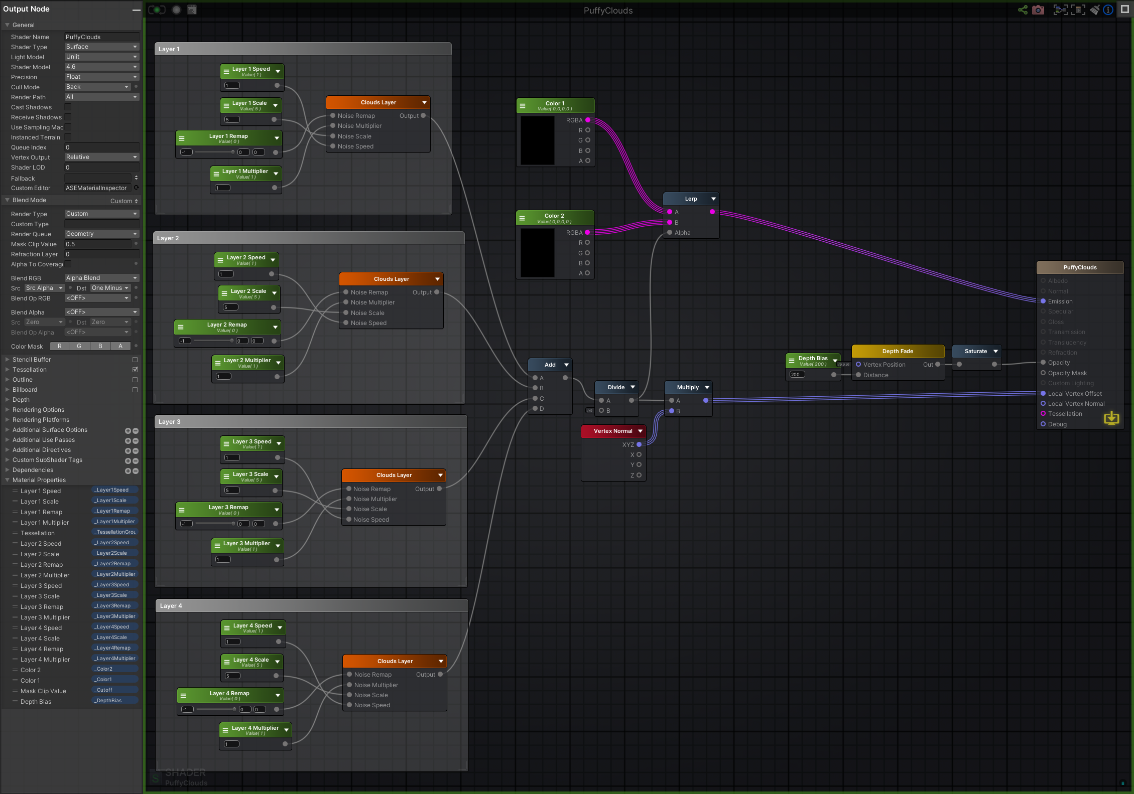
And, our functions:
Thanks for reading!